
What Thermal Noise Means Inside a Stacked CMOS Stack
Thermal noise becomes visible when heat-generated charge starts competing with the weak image signal collected during a long exposure. Sensor temperature and integration time both influence that charge. A multi-minute frame gives thermally generated electrons time to accumulate, especially in deep shadows where the useful signal may already be sparse.
Three artifact classes deserve separate treatment: dark-current shot noise, repeatable spatial structure, and discrete hot pixels. Dark-current shot noise contributes random variation. Repeatable structure can appear as warm corners, column patterns, or edge glow. Hot pixels occupy fixed coordinates and may brighten sharply as the sensor remains energized.
Separating those three prevents a common diagnostic error. One persistent bright photosite does not establish uniform thermal contamination across the frame, while a smooth-looking histogram does not rule out weak shadow signal-to-noise ratio.
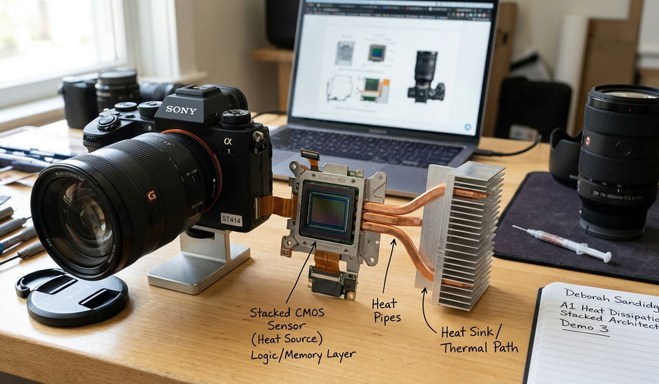
A stacked back-illuminated CMOS sensor places the light-sensitive photodiode layer on a separate die from the high-speed logic layer. The two layers share a bonded thermal path. Heat produced by active circuitry can therefore conduct toward the photodiode plane while also moving outward through the package and camera chassis.
Brief exposures often conceal this behavior. Multi-minute continuous integration exposes it because the sensor collects thermally generated charge for the entire frame, leaving warm edges, recurrent bright pixels, and subtle column structure easier to see after a controlled shadow lift.
How Heat Moves Through Bonded Logic and Photodiode Layers
Heat follows two relevant routes inside a stacked-sensor camera. The first crosses the bonded interface between the logic die and photodiode layer. The second runs outward through the sensor package, chassis, lens mount, and attached lens. Both routes operate at once, though their relative influence changes with the body, lens, enclosure, and camera state.
The logic die supports high-speed sensor functions and dissipates heat while circuitry remains active. Live view, image stabilization, display use, and firmware power management can alter how much of the system stays energized before and during an exposure. A sealed rain housing may also slow heat loss to the surrounding air.
Time structure matters. A 10-second frame followed by idle time gives the body repeated recovery windows. One uninterrupted 6-minute integration gives the stack no comparable pause. The photodiode layer continues collecting dark current while the camera has fewer opportunities to shed accumulated heat.
Trace Both Directions
When diagnosing a warm corner, photographers often concentrate on the sensor plane alone. A more useful reading follows heat across the bonded stack and then out through the body. A heavy metal-bodied lens may provide a different conductive path than a compact lens mounted inside an insulating cover.
A field log should record ambient air at the start, exposure duration, ISO, display state, stabilization state, and the delay since the preceding frame. The size and location of artifacts still depend on body design, enclosure, firmware behavior, and the subsystems left energized; similarly described stacked sensors can therefore produce different recovery patterns.
What Happens When Integration Runs Past Five Minutes
A controlled sequence makes heat buildup easier to distinguish from ordinary low-light noise. Begin after the camera has rested, then capture 30-second, 2-minute, and 6-minute raw files at matched ISO and aperture. Control exposure level through scene choice or neutral-density filtration rather than by changing sensor gain.
Keep focus and framing fixed. High ambient temperature, continuous live view, a sealed weather housing, or an extended burst immediately before the sequence can cause thermal artifacts to appear earlier, so the camera's recent workload belongs in the capture notes.
- Establish the reference. Make the 30-second frame after the body has rested and note any bright pixels already present.
- Inspect the middle duration. Use the 2-minute raw to identify early edge warmth, repeated pixel coordinates, or column structure.
- Read the long integration. Examine the 6-minute frame for stronger corner glow, more conspicuous fixed pixels, and increased variation in deep shadows.
- Normalize processing. Apply identical white balance and shadow lift, with sharpening and noise reduction disabled.
- Compare fixed regions. Check the frame center, all four corners, and any bright pixels recurring at identical coordinates.
The resulting progression requires careful interpretation. Photon shot noise follows the captured light signal. Dark-current shot noise arises from thermally generated electrons accumulated during integration. A hot pixel represents a local defect or high-dark-current site, so it should not be treated as evidence that every area of the sensor has warmed equally.
Warmth that strengthens along one edge suggests repeatable spatial behavior rather than a purely random increase. Scattered grain in a low-signal region may contain both photon and dark-current contributions. A bright point that returns at the same coordinate belongs in the hot-pixel map.
Inspect Raw Structure
Judge thermal behavior before creative treatment. Nik Color Efex Pro, sharpening, local contrast, and aggressive color grading can magnify minor defects or disguise their original structure. Keep the diagnostic pass neutral and repeatable.
Reading Signal-to-Noise Ratio Against Hot Pixel Growth
Can a correctly placed histogram coexist with weak shadow signal-to-noise ratio? Yes. The histogram summarizes tone distribution, but it does not isolate added dark-current variance, corner glow, or localized hot pixels.
Compare the 30-second, 2-minute, and 6-minute raws with identical ISO, aperture, white balance, demosaicing, and tonal adjustments. Place matched sampling areas over one smooth midtone and one deep shadow, then toggle among the files at the same magnification. The useful question is whether texture and tonal separation survive as integration length increases.
Rising thermal contribution can flatten usable dynamic range even when the mean exposure appears correct. Shadow lifting reveals the change first: fine tonal differences become harder to separate from random variation, while fixed warmth may consume part of the correction latitude near an edge.
Use Hot Pixels as a Trend
Evaluate hot pixels at 100 percent view before checking the intended print or display size. Count only pixels or small clusters that remain conspicuously bright against neighboring dark tones at the same coordinates. Their growth across the sequence provides a practical proxy for heat stress.
No universal count separates a usable frame from a failed one. Final visibility matters, especially for a blue hour cityscape where bright architectural points may hide isolated defects. A smooth long exposure of dark water exposes the same defects much more readily. Nik Silver Efex Pro can make persistent pixels conspicuous when tonal contrast rises, so complete the technical comparison before monochrome conversion.
Setting Cooling Intervals Between Long Frames
A cooling interval is powered-down or genuinely idle time that allows the bonded stack and camera body to shed heat before the next multi-minute frame. Its duration should reflect the preceding exposure and the camera's recent workload.
Start with something like a 2- to 5-minute powered-down interval as an initial field test after a multi-minute frame. Compare the next raw with the previous file at identical settings. If new bright pixels or edge glow continue to accumulate, lengthen the pause.
- Ambient air: Warm, still conditions slow heat transfer away from the body.
- Body exposure: An uncovered chassis can dissipate heat differently from a camera enclosed in an insulating weather cover.
- Lens mass: A heavy metal-bodied lens may conduct heat through the mount differently from a compact lens.
- Powered state: Live view, display use, stabilization, and other energized functions can reduce the value of an apparent idle period.
Avoid wrapping the body during the interval unless moisture protection requires it. If the camera offers no trustworthy sensor-temperature record, label files by capture order and elapsed time. An EXIF body-temperature field, when present, may describe another internal component rather than the photodiode layer.
Match Dark Temperature
Capture each dark with the same exposure time and ISO as its associated light, with no light reaching the sensor. Keep the dark adjacent to the light so the camera has not undergone a large thermal change. A dark made after substantial cooling may subtract the wrong pattern, leaving residual bright pixels or creating dark pits where the calibration frame contained stronger hot pixels.
Match the long-exposure noise-reduction setting and raw bit-depth mode as well. Thermal calibration depends on sequence context, not exposure duration alone.
The Protocol I Trust for Multi-Minute Stacked-Sensor Work
The field protocol I rely on repeats a work-and-cool cycle. Make the long light frame, cover the optical path, capture a thermally adjacent dark, and then allow the camera a deliberate powered-down interval before beginning the next integration.
Record the start time, frame duration, ambient condition, cooling interval, and preceding camera activity in a short voice memo or field notebook. After each cycle, inspect the same shadow region and corner with identical raw settings. Extend the pause when bright-pixel growth or edge glow continues across successive frames.
This approach also limits exposure-level risk. In critical night and astrophotography work, several controlled integrations preserve more options for calibration and selection than a single extreme take vulnerable to changing heat, passing light, vibration, or tracking error.
A Repeatable Field Cycle
- Capture the multi-minute light at the planned ISO, aperture, raw mode, and noise-reduction setting.
- Capture its matched dark while the body remains in a similar thermal state.
- Power the camera down for the chosen cooling interval.
- Review the same corner, shadow region, and recurrent pixel coordinates.
- Lengthen the next interval if thermal structure continues to grow.
Plan every multi-minute stacked-CMOS session as timed light-dark-cool cycles; this disciplined sequence protects shadow SNR and keeps hot-pixel maps manageable more reliably than chasing one ever-longer exposure.











Reader Comments
The conversation starts with you.
Your Comment